Fiber optic sensors have become a critical technology enabler behind the latest functional MRI (magnetic resonance imaging) suite upgrades and new MRI equipment designs. It is increasingly desirable to synchronize certain patient activity with the MRI imaging system. The incredible high magnetic field strengths are increasing with each generation (3.0 Tesla being the top of the line norm today) so that the electromagnetic transparency of components become more important with each succeeding generation and new application. The intrinsic passiveness and electromagnetic immunity of optical sensors plus the all-dielectric nature of optical fiber is ideal for both sensor design and optical signal transmission in and out of Zone 4 (MRI Scanner location) of the MRI suite.
Designing equipment that can operate within the extreme electromagnetic fields present in an MRI suite is extremely challenging. The MRI suite precludes the use of conventional components and structures fabricated from ferrous-based materials, nickel alloys and most stainless steel materials – including electronics, electric motors and other electrical and electromechanical devices commonly used in the industrial world. Magnetically attracted metals – small or large – can become harmful projectiles and either damage the machine or affect patient/operator safety. Also improper materials can create undesirable artifacts or distortions which affect the quality of the imaging results.
Our central focus is the development and application of MRI compatible fiber optic sensors necessary for closing the loop – specifically for measuring position, speed and limits. In this article we present three MRI-based motion control applications which demonstrate the operation and use of recently developed, commercially available MRI safe fiber optic-based feedback sensors.
Mythbuster: Fiber Optics Is Not Fragile
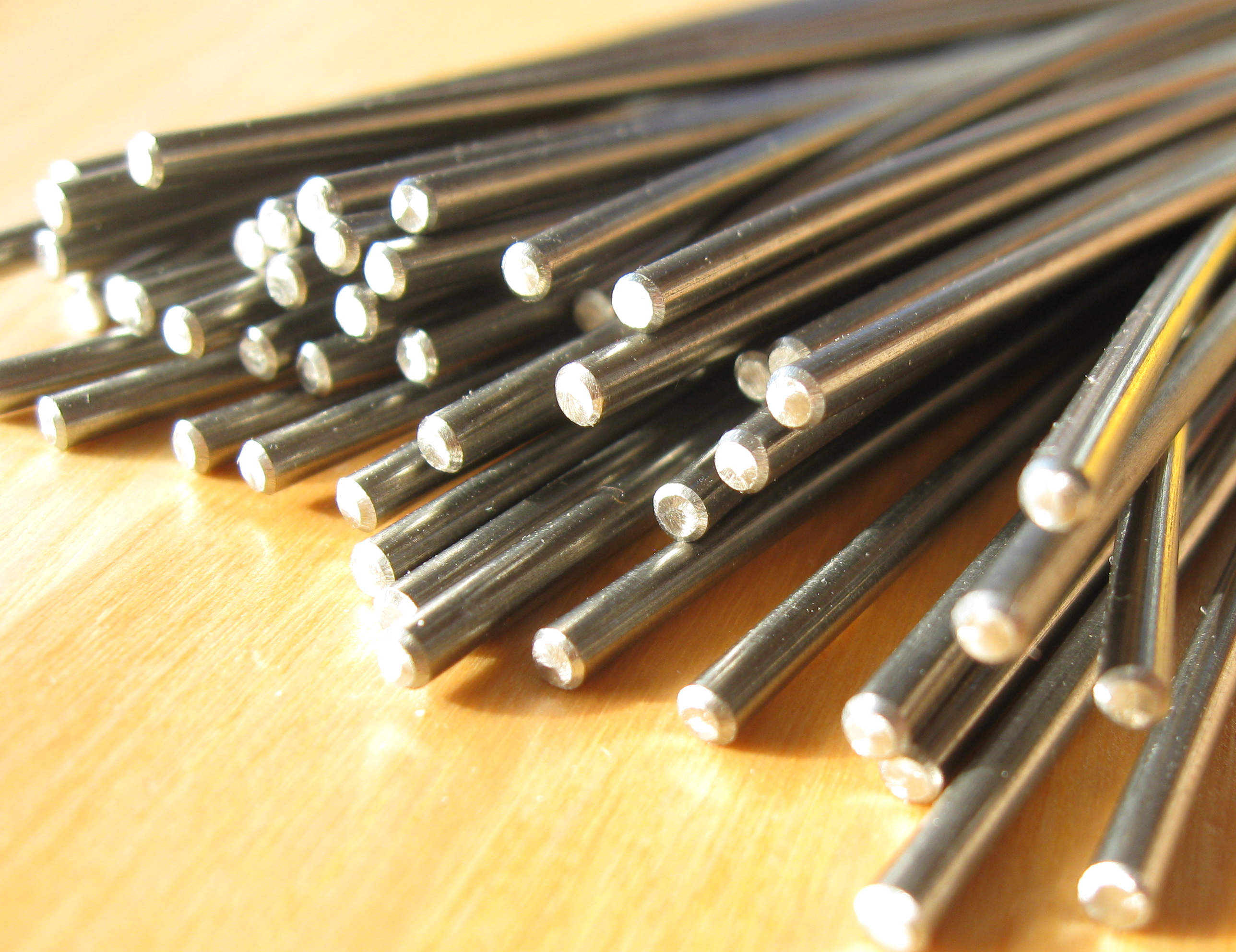
Although made of glass, fiber optics is not fragile. Optical fiber and cabling is designed to be strong and resistant to physical abuse – especially excess bending and high tensile loads. The military uses optical fiber in the harshest applications, including aircraft, missiles, satellites and the most hostile environments – from the desert to the arctic, from undersea to space.
It’s essentially just another type of wire – a glass wire.

What Is a Fiber Optic Sensor?
As shown in Figure 1, a fiber optic sensor is a device that alters the properties of the light passing through the device based on a physical quantity imparted on the device. In this sense, the fiber optic sensor is not a true transducer – it does not convert one form of energy into another – but is instead a “sensing element” which changes a characteristic parameter of the light injected into the sensor. Hence, a typical fiber optic sensor system consists of three parts – the fiber coupled “passive” optical sensor, the “active” interrogator or system interface, and the fiber optic light path or link that connects them. Because of its low loss and ability to transmit interference-free over long distances, the fiber optic link provides the means of locating the active interrogator/system interface outside the MRI Scanner (Zone 4) Area.
How Does a Fiber Optic Position Sensor Work?
Typically optical power (light) is sent to the sensor where the light is being altered or changed in amplitude, wavelength, polarization, etc. Other sensors measure the time of flight of the light while the physical property changes the optical path length.
The simplest form of a fiber optic sensor is an optic limit switch where the presence or absence of an object in the light path must be determined. In this case evaluating the ON-OFF state of light is sufficient and works reliably. To the fiber optic designer it is an unfortunate reality that optical amplitude within a fiber optic link is not stable and cannot be relied on for making absolute measurements. Long term source degradation, fiber bending and fiber optic connector non-repeatability all affect optical transmission over time and environmental factors severely affect measurement accuracy. Fiber optic communication links are reliable because they transmit digital information and all receivers incorporate an automatic gain control (AGC) amplifier.

Thus, position sensors that depend on light amplitude modulation have proven to be unstable, inaccurate and unreliable. Spectral-based techniques are much more reliable because they are not affected by light intensity. Whether the light level is low or high, the spectral light distribution in the fiber remains the same. For instance, Fiber Bragg Gratings are one such technology which alter the spectral behavior but are affected by temperature – making for a poor position sensor. The key optical innovation of the Micronor MR330 series MRI position sensor is that the position information is embedded into the optical spectrum and provides accurate, high resolution position information unaffected by varying losses or degradation in the fiber optic link. Utilizing the optical spectrum as the information carrier rather than amplitude assures reliable accuracy, even when the fiber link installation is degraded.

As shown in Figure 3, the interrogator/controller transmits a broadband light pulse to the sensor via the input fiber. Based on the position of the rotary code wheel, the internal optics passively convert this light pulse source into a return signal transmitted over the output fiber, in which the spectral pattern is essentially a unique binary representation of the rotary encoder’s angular position. Internally, the interrogator functions like a spectral analysis system in which the optical return signal is imaged onto a CCD and the resultant spectral signature analyzed and converted to an angular position code.
The second innovation of the MR338 MRI Safe Position Sensor is its fabrication from non-metallic materials so to be completely RF transparent. This was not a simple substitution of non-metallic materials versus the original MR332 “Metallic” industrial sensor design. Due to the accuracy required, the materials must be extremely stable over temperature, humidity and time. Internally the sensor accurately resolves down to 4µm thus any shift of the material introduces an error in position reading. There are numerous plastic materials that have a suitable low temperature coefficient, however, as is typical for plastics, they exhibit hygroscopic property which means they change size based on moisture content. A suitable ceramic-like material is used for alignment of the dimensionally critical optics. This part is fabricated using high precision stereo lithographic fabrication technology.
The resulting MR338 MRI position sensor system offers 13-bit (8192 counts or 0.044°) single turn resolution and 12-bit (4096 count) multiturn tracking. The same optical technique is also applied to a fiber optic linear position sensing system.
Case Study #1 – MRI Safe Patient Pedaling System for Validating fMRI Techniques
Functional MRI (fMRI) is the technique of using the MRI to observe brain function based on imaging blood flow and oxygen metabolism in the brain. One fMRI research area is the study of brain impairment caused by injury or strokes and the follow-on evaluation of the effectiveness of various treatments and rehabilitation techniques.

Marquette University designed the fMRI patient pedaling device shown in Figure 4 (left). Using the MICRONOR MR318 fiber optic incremental encoder output to monitor speed and angular position/leg extension, the experiments were successful in correlating specific motor activity with corresponding observed cortical brain activity. Some of the results are shown in Figure 4 (right) depicting functional images which correlate three unique motor activities (pedaling, foot tapping and finger tapping) to specific cortical activity areas in the brain. This initial study was the first time that human brain activity associated with controlled pedaling had been accurately recorded and correlated with fMRI imaging.
Case Study #2 – MRI Safe Device for Studying Mechanics of Traumatic Brain Injury (TBI)

The Henry M Jackson Foundation For the Advancement of Military Medicine (HJF) of the National Institute of Health (NIH) is investigating the mechanics of traumatic brain injury. As shown in Figure 5, the MRI safe device imparts a mild angular acceleration to the skull of a human volunteer inside an MRI scanner. An MRI compatible fiber optic absolute position sensor is used to measure angular position as well as capture instantaneous velocity and acceleration during an experiment. As shown in Figure 6, this data is then correlated in real time with the MRI imaging. The simulated trauma event takes place within approximately 400ms. The sensor system controller offers a hardware function that outputs a real-time trigger for synchronizing the MRI imaging to the head position within 0.04°. The fiber sensors high resolution of 8192 and fast update rate of 850µs allows a recording of some 500 data points for one event. With this amount of fine grained data available, the research team is able to extract both velocity and acceleration information from the recorded data.

Case Study #3 – MRI-Safe Treadmill for Advanced Cardiac Stress Testing
Heart disease is the leading cause of death in the United States. EXCMR Inc. has developed an MRI safe treadmill for advanced cardiac stress testing and heart imaging. MRI cardiac imaging provides superior imaging evaluation and patient safety over traditional nuclear or ultrasound techniques.By placing the treadmill in the MRI suite, EXCMR is able to do cardiac imaging immediately after exercise (within 30 seconds) before stress induced cardiac abnormalities can dissipate. These images cannot be acquired quickly enough if the treadmill is located remotely from the imaging system.
 The MRI Safe Treadmill is shown in Figure 7. It is operated immediately adjacent to the MRI Scanner (Zone 4) where certain approved metallic materials may be used. However active electronic equipment is not permissible. The motor is hydraulic powered and all feedback sensors must be electronically passive. The patient Emergency Stop (MR380), Treadmill Incline (MR340) and Speed (MR382) are purpose designed MRI safe sensors based on commercial fiber sensors by Micronor Inc. The three fiber optic sensors are connected to the Integrated Controller located in the monitoring room (Zone 3) via a heavy duty, 50-foot six fiber optical cable.
Conclusion
In conclusion, fiber optic sensor technology is a key enabler for the development of MRI safe motion control systems required for advanced medical research. Fiber optic sensors are inherently passive and immune to magnetic fields. Optical fiber provides an ideal all-dielectric transmission medium between the MRI Scanner (Zone 4) and the MRI Control/Equipment Rooms (Zone 3). Fabricated from the proper materials, MRI safe fiber optic sensors provide the electromagnetic transparency for safe use in and around the extreme electromagnetic field strength of the MRI Scanner. They are robust, easy to install and do not create artifacts or otherwise affect imaging results even when used inside the MRI bore.
————————————–
The authors wish to acknowledge the following people for their special contributions to this article:
- Dr. Sheila Schindler-Ivens, Associate Professor, Dept of Physical Therapy, Marquette University, Milwaukee-WI. With additional permission from Elsevier for photos reprinted from the Journal of Neuroscience Methods, Volume 179, Issue 2, Dr Sheila Schlinder-Ivens et al, A novel technique for examining human brain activity associated with pedaling using fMRI, pages 230-239, Copyright 2009 by Elsevier.
- Dr. Andrew Knutsen, Postdoctoral Fellow, The Henry M Jackson Foundation For The Advancement of Military Medicine, National Institute of Health, Bethesda, MD.
- Mr. Vijay Balasubramanian, Product Development Engineer, EXCMR Inc., Columbus, OH.