Darren Bjork | Vice President, Medical | Metro Mold & Design
Narrowing the gap between design requirements and what’s possible is always a major challenge for medical-device manufacturers. When only eight to nine months are available to transition from a manual assembly process to a more scalable method, a successful transition calls for drastic measures.
This was the case for a major medical device manufacturer when it was looking for a more efficient way to manufacture a 6-French subassembly for an atherectomy device, designed to remove plaque from arteries. A significant portion of this part’s manufacturing process was done by hand, inhibiting scalability, increasing risk, and raising costs.

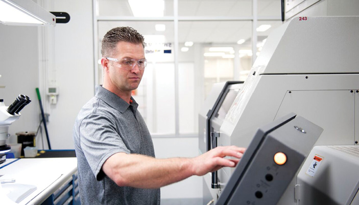
The MMD team discusses the next steps after inspecting molded parts from a development tool. The relatively inexpensive prototype mold showed what could work and how well. The production mold then incorporated all lessons learned with modifications for a more automated production.
Design for manufacturing
The previous design included a small machined scoop connected to a clear tecothane tube housing a lumen. A platinum marker band was crimped around the top to let a surgeon clearly identify the device’s location under fluoroscopy during surgery. The tube geometries were not conducive to a robust molding process, so a piece of cellophane-like plastic was wrapped by hand around a wire holding the lumen, marker band, and scoop. When heated by a flame, the plastic shrank, compressing it tightly to the wire. This was repeated with additional layers until the part was built up to a proper size.
Although the process resulted in acceptable parts, it involved substantial labor and a high risk of failure. Because the subassembly had to mate to another machined part, any variation created through the manual process meant a “trial and error” fitting was needed to match components perfectly during assembly. Countless hours and dollars were expended through this inefficient manufacturing process.
When asked for assistance, our team at MMD Medical began by looking at this challenge holistically. This method was derived from our combination of skill sets and perspectives, based on our experience with multiple manufacturing disciplines. The approach led us to believe that injection molding was a possible alternative to the manual process.
Knowing that the part geometry could not be changed, two distinct challenges stood in the way of injection-molding the plastic over the lumen, marker band, and scoop:
- Alignment of multiple complex components: The gate location would be critical; high pressure from the injection-molding process could deflect the lumen, creating an unacceptable part. Gate and tool design were the keys to minimizing this effect.
- Robust process window: Because the molded plastic had to shut off on the scoop without flashing, and the wall was extremely thin, it was difficult to avoid ending up with a short-shot, or overcompensating and creating flash.
Our team began collaborating with the customer’s engineering team to the point that we became extensions of one another. Working quickly to identify what was going to work and what wasn’t, we worked side-by-side, making decisions and significantly shortening the time frame.
Each team brought significant skills to the collaboration table. One team knew the design while Metro Mold & Design provided expertise in manufacturing.
Getting started
To understand how to design a more efficient, repeatable solution, the teams began to consider the possibilities. Ultimately, the discussion led to the creation of a development tool — a test mold. Given the complexities of the application, it was more efficient to create a low-cost prototype tool than conducting a mold-flow analysis. We believed we would learn far more about the viability of injection molding from the tool’s performance.
Based upon this decision, we built a proprietary development tool to better understand how the subassembly could be molded. Normally, development tools are used to test and tweak geometry, gate location, and other performance factors, but we knew we had to make sure this initial bare-bones tool would work at a basic level. We built it of steel to ensure the part would fill; once it was built and tested, we confirmed our hypothesis that we could develop an injection-molding solution to replace the existing manual process.
Our team then developed a second tool to test how it would work in production, given the complex geometries of the subassembly. Based on what we learned from the first tooling iteration, we were able to further optimize gate size, gate location, and molding parameters. We also made sure to use the same mold base for both development tools to maintain overall cost savings.
When building the second development tool, a main consideration was making sure we could move the gate location 180° if necessary. This would let us manipulate the tool to determine exactly how to maintain the proper positioning of the lumen within the subassembly during the molding process.
The ability to move the gate around, along with other minor tool adjustments, gave us crucial insight into enhancing repeatability and scalability, and to predict component wear patterns. This information would ultimately lead to the development of a more durable and efficient production tool.
After developing the second tool, the teams working on the subassembly were ready to hit the aggressive product launch date with a more efficient process. The collaboration of both teams provided a shortened learning curve and led to the development of a reliable production tool – built for optimized efficiency and longevity.

With the in-house capabilities to machine a previously outsourced component that was often delivered late, it became clear that we should make it ourselves.
The next generation
With the new, reliable, scalable process and design in place, it was time to address a significant supply chain challenge. A supplier for the subassembly’s machined scoop was proving unable to keep up with product demand. Due to lack of capacity, it didn’t have the machine time to keep up with the aggressive lead times for the development process.
Because we have the in-house capabilities to machine the component, it became clear to the customer that we should make it ourselves. This would streamline the supply chain, drastically reduce lead times, and let us maintain the quality control needed to ensure consistent, successful runs. Leveraging our vertical integration let the customer get the part machined in weeks rather than months.
We were able to further drive out costs by eliminating additional components on the next-generation design. For instance, making the previously clear tube out of a radiopaque material meant that the marker band was no longer needed. The entire component would now be visible with a fluoroscope. Eliminating a single component resulted in reducing both inspection and material expenses, slashing cost and making the device more competitive in the marketplace.
Final thoughts
By seeing what was possible in a difficult situation, a talented team forged a relationship that led to increased business and success for both companies. A broad range of in-house capabilities and perspectives led to the manufacturer’s willingness and capacity to take on multiple challenges for its customer as well as find ways to streamline production, reduce costs, and provide a higher quality product. This relationship inspired innovation from both parties and resulted in capturing market share that would have otherwise escaped.