The Project: Enhance the critical attributes of an x-ray system without adversely impacting the design time.
The Solution: Use an electromagnetic simulation software solution to evaluate the proposed design.
By Dr. Cris Emson
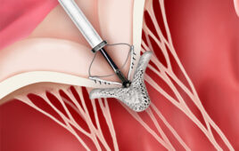
| Figure 1: Cross section of cathode head (or electron source, at bottom) and target (or beam dump, at top), with simulated electron beam trajectories and equipotential lines (100 kV/500 mA). |
| Figure 2: Simulated electron beam cross section plotting current density (-J) vs. position on target (1 mm width, 100 kV/500 mA). |
| (Click on an image to enlarge) |
Computer simulation is helping Varian Medical Systems Inc. of Salt Lake City, UT reduce the time required to design x-ray sources for computed tomography (CT) and other medical equipment by 75%. The critical concern for many medical device manufacturers is to increase x-ray intensity, improve x-ray source distribution profile, and reduce the dimensions of the focal spot. The challenge is that increasing the intensity or density of the beam causes the electrons (within the beam) to repel each other more strongly, which in turn increases focal spot dimensions. The goal is to develop beam forming structures that improve source density profiles and reduce the dimensions of focal spots on beams with increased space charges and self repulsion effects.
In the past, a long trial and error process that typically took about six months was required to meet customer specifications for a new custom design. Using Opera from Vector Fields, one of the few electromagnetic simulation software packages that takes beam self-repulsion effects into account, Varian has been able to dramatically reduce design time by building an electromagnetic simulation model that makes it possible to quickly evaluate alternative configurations without the need for building prototypes. The ability to accurately evaluate proposed designs in software with beam self repulsion and space charge effects taken into account has helped reduce the typical time required to develop new designs to only six weeks. The result is that Varian has reduced engineering costs while being able to provide shorter delivery times to its customers.
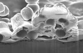
| Figure 3: Cross section of cathode head (or electron source, at bottom) and target (or beam dump, at top), with simulation predicted space charge density (-rho)(100 kV/500 mA). Note correct prediction of increase in space charge density proximate to adjacent cathode edges. |
| Figure 4: Magnified cross section of cathode head (or electron source, at bottom) and target (or beam dump, at top), with simulation predicted space charge density (-rho) (100 kV/500 mA). Note correct prediction of increase in space charge density proximate to adjacent cathode edges. |
| (Click on an image to enlarge) |
Reducing X-Ray Dosage
The key is to reduce the dosage received by patients while improving diagnostic accuracy—to increase the intensity of the x-ray in the area under examination while reducing extraneous rays that add nothing to the diagnosis but do increase the patient’s dose. The trouble is that electrons, like all objects with the same charge, repel each other. So increasing the beam intensity or density causes the electrons (within the beam) to spread further apart from each other. The designer’s challenge becomes managing a series of tradeoffs that are typically required to meet the customer’s objectives. In the past, Varian engineers had very limited ways to evaluate the effectiveness of a proposed design except to build and test a prototype. The problem is that each physical iteration costs about $40,000 and takes about six weeks. An average of three or four iterations was typically required to meet the design specifications. Most of the time was typically involved in meeting customers’ requirements for focal spot size, focal spot character, and beam current. An uneven x-ray intensity distribution within the focal spot is another problem that often had to be overcome.Varian has used software for a considerable period of time to simulate the performance of an x-ray source by modeling the electron beam focusing structure within the x-ray tube. But the software used in the past, while providing rough guidance, did not accurately predict the all-important focal spot dimensions and focal spot characteristics. One problem was that the software was configured to only handle a cylindrical geometry so the more complicated geometry of real-world sources had a negative impact on its accuracy. Another problem was that the software did not correctly account for the mutual repulsion of the charged particles within the beam in determining the focal spot.
As a result, the program typically predicted focal spot dimensions about twice the actual size.“This meant that we had to perform a series of physical tests that took about seven to ten days to determine a scaling factor for each modeled configuration that could be used to calibrate the simulation,” said Lynn Chidester, Varian Medical Systems Engineer. “Once the scaling factor was determined for a given beam focusing geometry, the simulation was able to predict the focal spot with a fair amount of accuracy and was also able to make accurate relative predictions about the performance of two different configurations within the same geometry. We looked at other software packages but could not find any that met our critical requirement of being able to take beam mutual repulsion and space charge effects into account.”
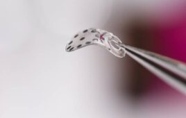
| Figure 5: Cross section of cathode head (or electron source, at bottom) and target (or beam dump, at top), with simulated electron beam trajectories and equipotential lines (compare to Figure 1, but at 100 kV/100 mA). |
| Figure 6: Simulated electron beam cross section plotting current density (-J) vs. position on target (compare to Figure 2 , but 2.0 mm wide, 100 kV/100 mA). Note correctly predicted beam density profile changes with beam current (500 mA vs 100 mA). |
| (Click on an image to enlarge) |
Accounting for Self-Repulsion
“Vector Fields’ Opera was the first software package I tried that was able to accurately simulate the operation of an x-ray source,” Chidester said. “The key to its accuracy is its ability to account for the repulsion of the electrons and other charged particles that tend to spread or modify the electron beam.” Chidester typically begins by generating a family of models with both 2D and 3D models of the concept design. He defines the models by specifying the electrostatic and electromagnetic beam forming and focusing structures based on the part configurations, voltages, and magnet/coil positions. Once the initial model is developed, the time required to evaluate additional design iterations is reduced to less than an hour.In addition, computer simulation provides considerably more information on the performance of the design. As opposed to the beam profile at target position only measurements provided by physical experiments, engineers can obtain beam profile measurements at all positions along the beam path within the model. These beam profile graphical presentations are so easy to follow they can considerably increase the understanding of the functions of the electron beam focusing structures within the design.
“Soon after I began using Vector Fields, I developed enough proficiency that I began obtaining results very close to the x-ray focal spot measurements that I took with a pinhole camera,” Chidester said. “Both the focal spot size and the intensity distribution within the focal spot in the simulation correlate very well to test results. This made it possible to eliminate the need for a scaling factor, which dramatically reduced the time required to analyze a new design. It now takes an hour or less to set up the 2D model geometry and run the analysis for a new design. For 3D models, design iterations can be accomplished in only a few hours. The confidence that we have developed in the accuracy of the simulation has made it possible to use simulation as an integral part of the design process. The majority of the design process is now focused on simulation, which proceeds at a much faster pace than physical prototyping. We now develop and optimize the design in software and only begin prototyping in the late stages of the design process as a validation step. Where we might have made three to six prototypes in the past, we now need just one or two.”
Substantial Reduction in Engineering Time and Expense
“The ability to develop new products with software rather than hardware prototypes has become particularly important in recent years as medical device manufacturers have put increasing emphasis on providing higher resolution x-ray images while reducing the x-ray dosage transmitted to patients,” Chidester said. “For the x-ray source supplier, this often translates into smaller focal spots, improved x-ray distribution, and increased x-ray intensity. The design process has become more challenging than ever before because the more we design the x-ray tube structures to focus or shape the beam, the more the beam counteracts our efforts through self-repulsion. To coin an analogy, we find ourselves wandering in the middle of the Arabian desert trying to get from Riyadh to Mecca. Opera provides us with a GPS system that allows us to make immediate course corrections to move towards our destination as quickly as possible.”| Figure 7: Cross section of cathode head (or electron source, at bottom) and target (or beam dump, at top), with simulation predicted space charge density (-rho) (compare to Figure 3, but at 100 kV/100 mA). Note correctly predicted of space charge density differences proximate to adjacent cathode edges, and differences in space charge density with beam current (500 mA vs. 100 mA). |
| Figure 8: Magnified cross section of cathode head (or electron source, at bottom) and target (or beam dump, at top), with simulation predicted space charge density (-rho) (compare to Figure 4, but at 100 kV/100 mA). Note correct prediction of increase in space charge density proximate to adjacent cathode edges, and differences in space charge density with beam current (500 mA vs. 100 mA). |
| (Click on an image to enlarge) |
As an example, Chidester pointed to a recent case where a customer requested a custom version of an existing x-ray tube with a smaller focal spot and a higher beam current. “The previous design had a 2.0 mm focal spot and a 100 mA beam current,” he said. “The customer said that they would like to have a 1.0 mm focal spot and a 500 mA beam current with reduced off-focal radiation. Previously, we would have gone through numerous model, build, and test iterations, gradually optimizing the size and character of the focal spot. With OPERA, on the other hand, we were able to see the effects of self-repulsion right off the bat and quickly move through the design space to evaluate the effect of various amelioration strategies. We also minimized off focus radiation within the desired focal spot intensity distribution and developed a design that met our customer’s requirements in only six weeks with only one physical prototype. Our success in this example is typical of the results that we have achieved through simulation over the past several years. As a result, we have been able to meet our customers’ requirement for higher performing sources in less time at an economical price.”
Sidebar: The Case Customer
Headquartered in Palo Alto, CA, Varian Medical Systems Inc. is a leading manufacturer of integrated cancer therapy systems as well as x-ray tubes and flat-panel sensors for imaging in medical, scientific, and industrial applications. The company employs approximately 3,280 people who are located at manufacturing sites in North America and Europe and in sales and support offices around the world. Its x-ray products business is the world’s largest independent x-ray tube manufacturer. Varian x-ray products produce high-performance x-ray tubes for imaging applications and flat panel detectors for fluoroscopic, angiographic, and cardiac applications. Offering over 400 different types of replacement tubes, the x-ray products business is also home to Varian’s new amorphous silicon digital radiography product line. The company is evolving its x-ray sources for CT equipment to assure that the radiation dose administered to patients during CT scanning is as low as possible while creating usable images.ONLINE
For additional information on the products and technologies discussed in this article, see the following websites:
• www.varian.com
• www.vectorfields.com
Dr. Cris Emson is the vice president of Vector Fields Inc., 1700 N. Farnsworth Ave., Aurora, IL 60505. He earned his PhD from the University of Wales Swansea on special finite element techniques for unbounded electromagnetic propagation problems. Emson maintains specialized knowledge of all the Vector Fields software and particularly for high frequency applications using the Concerto package. He can be reached at 630-851-1734 or cris.emson@vectorfields.com.