By: Sabine A. Goodwin, CD-adapco,
C. Wadhwani, BDS MSD
K.H. Chung, DDS PhD

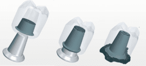
Parameterized model of implant abutment and crown.
Cements are commonly used in dentistry, but there is very little knowledge of how their flow patterns influence the performance of dental systems. One area in dentistry where shape optimization should be considered is cementing of implant restorations. It has been shown that extrusion of excess cement at the crown-abutment margin during the seating of a cement-retained crown over an implant is a major cause of peri-implant disease [1-4]. Recent advances in simulation are now enabling an increased level of insight into the details of the cement flow in these complex systems, opening the door for addressing the potential health issues associated with them and developing innovative implant designs.
Systems Control Solution
The cements used in dentistry are non-Newtonian and shear-thinning in nature [5]. This means that as more stress is applied, the cement starts to flow more readily. The stress in the system and therefore the implant shape are expected to significantly influence the flow patterns of cement including the volume of extrusion of cement into the surrounding tissue and the magnitude of extrusion forces. These parameters have a significant impact on the surrounding periodontal tissue [3,4] and may lead to long term peri-implant disease, a destructive inflammatory condition affecting the gums.
The problem of peri-implant disease as it relates to cement extrusion must be addressed from a “systems control” solution. Understanding cement flow patterns, appropriate placement sites and controlling volumes are all critical for finding ways to address the ongoing health issues associated with cement-retained implant restorations.
Crude models have been used to gain some understanding of cement flow, including using clear plastic beakers to visualize the behavior and studying implant abutments with cast crowns. Using a “design-build-test” principle in which the effects of design changes are quantified by experimental tests on physical prototypes is often costly and time-consuming [5, 6]. Simulation, on the other hand, opens the door for virtual prototyping and the dental industry is now beginning to better understand their complex systems by taking advantage of the benefits numerical simulation has to offer. This is destined to result in a paradigm shift within the dental field.
Numerical Approach
STAR-CCM+ was used to perform numerical simulations on the complete implant abutment, cement, and crown system.

Mesh and cement loading for simulations with STAR-CCM+.
Realistic implant abutment and crown forms from scanned stereo lithographic (STL) files provided data points for parameterization of the implant shape (Figure 1) and a polyhedral mesh was developed utilizing the overset meshing technology available in STAR-CCM+ to simulate the relative motion of the crown as it travels over the implant. The Volume of Fluid (VOF) multiphase model was used to simulate the flow of cement in the system as it is particularly well suited for immiscible fluids (like cement and air) and it enables capturing the position and shape of the interface between the dental cement and surrounding air as the crown is seated. RelyX cement (3M ESPE) was chosen for this study and its non-Newtonian properties were simulated using the Herschel–Bulkley model for non-Newtonian fluids in STAR-CCM+.
Figure 2 depicts a cross-sectional cut through the overset mesh, showing volume fraction of cement at the start of the simulation, with red representing 100% cement and blue representing 100% air. In this case, 35mm3 of cement was loaded near the crown margin, in a ½ toroid shape [7].

Abutment modifications (top) and effects of modifications on cement retention (bottom).
Observations in the lab
Recently, Wadhwani et al [6] have studied how implant abutments can be modified to control cement flow patterns and minimize cement extrusion. The in vitro study was performed on three types of abutments shown in Figure 3 (top row):
- A closed abutment (CA), with the screw access channel sealed off.
- An open abutment (OA) with the screw access channel left open.
- An internal vent abutment (IVA) with two additional round vents placed in the axial walls of the OA, 180⁰ apart.

Experimental data showing amount of cement retained in each system during laboratory experiments (CA, OA, IVA).
Figure 4 shows how much cement was retained in each system in the lab, clearly indicating that the amount of excess cement extruded at the crown-abutment margin was greatest for the CA, followed by the OA and the IVA. The photographs in Figure 3 (bottom) also reveal that there is a better infill of the screw access channel with the IVA abutment as compared to the OA abutment.
Simulate the system with STAR-CCM+
Numerical simulations enable the engineer to build a virtual laboratory, providing insight into a product’s performance before tests need to be carried out. State-of-the-art visualization tools available in STAR-CCM+ offer a wealth of detailed information not readily available from laboratory tests or from observations in the dentist’s chair, including visualizing the flow of cement in the system (Figure 5).

3-D images generated in STAR-CCM+ showing the details of cement flow during crown seating on the CA.
Using STAR-CCM+, the effects on the cement flow patterns were studied by varying four variables in the system: 1. Implant abutment design; 2. Cement application site; 3. Speed of crown seating; and 4. Amount of cement in the system.
Implant Abutment Design
First, the three types of abutments were analyzed and simulation results were compared to the findings from the experimental study [6]. This served as a validation of the numerical methods used. Figure 6 shows the geometry of the three models (CA, OA, IVA) in STAR-CCM+.

Geometries for each type of abutment: CA, OA, IVA.
 Figure 7 depicts the solutions obtained with STAR-CCM+ for each of the abutment modifications, showing the fraction of cement at the starting and ending positions for each of the systems. In this simulation, the cement was loaded in the shape of a ½ toroid near the margin of the crown and the crown travelled at a speed of 7 mm/sec. The amount of cement in the system was identical for each of the three abutment modifications shown (~35 mm3). Numerical simulations for each of these geometries showed realistic cement flows and predicted the trends observed in previous studies. As observed in the lab, the simulations predicted that the amount of excess cement extruded from the system is significantly larger with the CA system as compared to the OA or IVA system. The IVA is observed to be the best performer, with almost no cement entering into the surrounding environment. The simulations also support the observation that there is a better infill of the screw access channel with the IVA system compared to the OA system.
Cement application site

Cross sectional frames showing cement flow for two types of cement loading: near the margin of the crown and near the occlusal surface of the crown.
STAR-CCM+ was used to evaluate how cement application site affects cement flow patterns. Figure 8 displays the results of two simulations where the same amount of cement (~35 mm3) was loaded in a ½ toroid shape near the margin of the crown in the first case and in the occlusal half of the crown in the second case. Five cross sectional frames are shown as the crown is seated on the CA. Results indicate that when cement is applied high up in the crown, the occlusal space fills up much faster as compared to the case where it is loaded at the crown margin. Once the occlusal space is completely filled, pressure on the cement below it increases significantly. As a result, the extrusion of cement happens much earlier when loaded in the occlusal half of the crown; it leaves the system even before the crown fully seats. In the final position, this causes an incomplete margin seal, a greater extrusion site and an increased mixing of air and cement as it exits the system.
Speed of crown seating
Simulations were performed with three different speeds of crown seating to assess the effect of speed on cement flow patterns for each abutment modification.

Effect of speed of seating on cement flow in the CA system.

Effect of speed of seating on cement flow in the IVA system.
Figure 9 shows the final position for the CA, when the crown is seated in 0.25 sec versus 1 second. It shows visually that the crown should not be seated too rapidly if the seal is to be maintained. Figure 10 shows the results for the IVA system. In this case, a higher seating speed is beneficial, as it enables filling up the screw access hole completely, before cement is extruded in the surrounding environment. A similar behavior for the OA system was observed.
Amount of cement in the system:
The effect of overloading the crown with cement has also been evaluated. Figure 11 shows the IVA system with cement loaded in a toroid shape containing 30 mm3, 35 mm3 and 45 mm3 of cement. These results indicate that loading the crown with too much cement causes cement to be forced out at the cement margin, yet resulting in an incomplete fill of a screw access hole when internal venting is used. Similar results were obtained for the CA and the OA system.

Effect of amount of cement for the IVA system.
Conclusion
STAR-CCM+ was used to analyze the complex flow fields associated with cementation of implant restorations, opening the door for virtually addressing the health problems associated with extrusion of cement into the soft tissue surrounding the implant. Great insight was gained into the cement flow patterns for various cement application techniques and abutment modifications. Simulations with STAR-CCM+ predicted the patterns observed in recent experimental test making it well-poised for future studies. This is destined to result in a paradigm shift in the dental field.
References
[1] Pauletto N, Lahiffe BJ, Walton JN. Complications associated with excess cement around crowns on osseointegrated implants : a clinical report. Int J Oral Maxillofac Implants 1999;14:865-868. [2] Gapski R, Neugeboren N, Pomerantz AZ, Reissner MW. Endosseous implant failure influenced by crown cementation: a clinical case report. Int J Oral Maxillofac Implants 2008;23:943-946. [3] Wilson TG. The positive relationship between residual excess cement and peri-implant disease [4] Wadhwani C, Rapoport D, La Rosa S, Hess T, Kretschmar S. Radiographic detection and characteristic patterns of residual excess cement associated with cement-retained implant restorations: a clinical report. J Prosthet Dent. 2012 Mar;107(3):151-7 [5] Wadhwani C, Chung HK. The role of cements in dental implant success, Part 2. Dent Today. 2013 Jun;32(6):46, 48-51 [6] Wadhwani C. Piñeyro A, Hess T, Zhang H, Chung K.. Effect of implant abutment modification on the extrusion of excess cement at the crown-abutment margin for cement-retained implant restoration. Int J Oral Maxillofacial Implants 2011;26:1241-1246. [7] Wadhwani C, Hess T, Piñeyro A, Opler R, Chung KH. Cement application techniques in luting implant-supported crowns: a quantitative and qualitative survey. Int J Oral Maxillofac Implants. 2012 Jul-Aug; 27(4):859-64.


