Ken Gredick |
Manager of Manufacturing |
Triangle Manufacturing Co. |
Design for manufacturing (DFM) is the engineering art of designing products so that they’re easier to manufacture. There are multiple levels of DFM, but the one that affects our company the most is design for manufacturability for CNC machining.
DFM is a process in which the manufacturer communicates with the designer to establish a technical data package (print and specs) that has optimal machining geometry with specs that meet the design intent.
Design for Inspection (DFI), a related discipline, involves engaging designers and quality engineers to ensure that the print portrays the proper callouts to help streamline inspection techniques. With growing quality controls in the medical industry, inspection becomes a big challenge, especially when the print is not clearly defined.
An approach to DFM/DFI
There are many ways to approach the DFM/DFI process. Medical device engineers put hundreds of hours into designing an assembly and are justifiably proud of their new product. Eventually, they share their hard work with a manufacturer for a quote. After the quote is accepted, placing a production order kicks off the DFM/DFI process.
When the manufacturer approaches the OEM with a DFM/DFI activity, the team must know its audience. After spending hundreds of hours on a design and technical data package, most engineers believe their work is just about done, or even complete. But most of the time, that’s not the case. For starters, the prints occasionally need a significant amount of cleanup.
Approaching a new customer or design engineer is one of our greatest challenges. Everyone is different. We’ve found success with the following approach:
First, conduct a meeting to fully understand the assembly and function of the manufactured part or set of parts. If it’s an implant, we ask the engineers to review the risks of the implant. For example, an edge round may be a simple break-edge to the manufacturer, but for an implant, it may mean that tissue gets snagged on that sharp edge which can cause irritation to the patient.
Second, information from the first meeting lets the manufacturer better understand the critical dimensions and start making a list of design details that may have to be held close. The manufacturing team also gets an idea how to work with the design engineer. A positive sign is when the design team asks for feedback regarding the drawings.
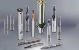
The prints should be reviewed in light of using standard tooling. For example, pay attention to:
- Fillet radii. They should be large enough so an end mill or boring bar can take a normal tool cut path.
- Use standard coatings as often as possible. Validations become costly when you start moving toward custom coatings.
- Design out costly manufacturing steps, such as die-sinking EDM.
 In parallel, the prints should be reviewed so that everything is dimensioned – not double-dimensioned – that data are clear and the GD&T is correct. All run-outs should be true-position (if possible) and with the understanding of the assembly, the manufacturer should request modifiers, such as Max Material Condition (MMC) and Least Material Condition (LMC), where appropriate. When used properly, these modifiers give the manufacturer more tolerance to make the part without changing the design intent.
A bolt-hole pattern provides an effective example of MMC use. If you have a plate with six dowel pins pressed in, and it is to mate with another plate with holes, a true position callout with MMC would be beneficial for the plate with holes. The larger the holes, the more true position tolerance they can have with the assembly still working. Such tools are mostly overlooked but provide great value to the manufacturer.
For DFI, the manufacturer should gage the print callouts to make shop-floor inspection techniques quick and effective. Automation, such as CMM and vision systems, is great, but it’s costly and cannot be at every work center. GD&T callouts must be straightforward, and both parties should have the capability to capture this data correctly and consistently.
Unless you have great working relationships with the design engineers, the manufacturer should not push the boundaries by going overboard with constructive criticism. An example would be redlining all features and wanting changes to everything, even when the print is not that good.
Instead, we like to organize design details into three categories for manufacturing and inspection. The designer should be able to identify each detail either as a:
- Must-have.
- Needs clarification. A good example of a ‘clarification’ is when a designer puts a datum on a centerline of multiple features, not one. This leaves the datum axis open for interpretation and needs clarification.
- Nice-to-have. It’s possible, for example, to produce a 0.003-in.-max radius described on a print. However, there are benefits on tool wear and feeds and speeds if the radius is increased to a 0.018-in. max.
Start with the Must Haves for print updates. Afterward, and judging how well identifying the must-haves went, follow with clarifications. These need not be print updates. But follow up with an email summary to document the discussion. Identify the Nice-to-Haves design details only when things are going well. Most of the time, the Nice-to-Haves should be left off.
In one of our most successful DFM applications, we had sufficient time and got paid for experimenting with questionable drawing callouts. We experimented with a hard coat anodize thickness to get an exact deviation in both its size and color. Soon after, this project went into production with few issues.
Meetings that discuss and resolve these matters can make or break a project, sometimes even a customer. The customer can either appreciate the service, find it distracting to the project’s time constraints, or even interpret the effort as an insult. It‘s imperative to correctly judge customer reactions and act appropriately. If such discussions go wrong, the customer may want to end the business relationship. When they go right, money will be saved for both the manufacturer and designer.
The payoff
A few benefits to a productive design and manufacturing discussion include:
Cost reductions that come from:
- Reducing or eliminating expensive manufacturing techniques;
- Reducing scrap because of optimized print callouts
- Streamlining inspection techniques; and
- Standardized tooling allows using off-the-shelf verses custom.
A manufacturable design and shorter lead times.
DFM/DFI meetings are excellent for team-building, an exercise that helps projects get started correctly. The key is to get involved as early as possible in the design stage. Having a good working relationship and communications with the customer always helps the process go smoother. This is how customer relationships are built to have a lasting effect on the business.

