Microscopes have been around since the 17th century. Since then, developments have increased the viewable area, the speed at which objects are located, and throughput. The microscope stage has been a major player in making these developments possible. Motorized versions have eliminated lateral stage drift, and enabled the gathering of sequential images of two or more view fields during time-lapse sequence acquisition and large-scale microphotography.
The drive mechanisms for microscope stages
can be divided into three basic categories: manual, step motor, and
piezoelectric. Manual drives and step motor drives have been viewed as
the gold standard, partly because they move over long distances. By
contrast, piezoelectric transducers move over very short distances but
with much higher resolution.

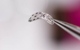
The LLC6, from Wegu-Device Inc. is a precise linear lens changer with six lens ports for ultra fast, automatic lens changing without the need of re-qualifying the lens. It suits TFT-LCD andphotomask inspection/repair applications or other tasks where multiple optical magnifications are required. It is driven by a linear shaft motor from Nippon Pulse America.
The travel range of a typical motorized stage is 2 to 4 in. in both the X and Y directions. Following is a look at the basic make up of each standard drive system, along with their advantages and disadvantages.

process, it’s important to be clear about the differences between
accuracy and precision. Accuracy is the ability to get closest to the
expected true point. Precision measures the ability to repeat a move
and get back to the same point, regardless of accuracy.
The ideal results for a microscope stage would be a command movement line (figure 1).

Figure 1. Microscope stages can be driven by manual, stepper, or piezoelectric motors.
The travel range of a typical motorized stage is 2 to 4 inches in both the x and y directions.
Step motors
Most step motor stages target resolutions of 1 µm or larger. Only a few systems using microstepping claim 10 nm resolution. These systems are typically limited to a speed of 100 mm/sec or slower, with a few low-resolution systems moving as fast as 250 mm/sec.
Steppers offer a number of advantages — there is no drift or jitter, they are durable and precise in full step mode, and there is no need for external feedback. If set up properly, a de-energized stepper stage can operate as a manual stage.
Disadvantages include the noise issue inherent to step motors. A stepper stage can be set-up for speed or resolution, but not both. If an encoder is not used, it is possible for the system to become inaccurate in its movement due to the system loosing steps (figure 2).

Figure 2. A stepper stage can be set up for speed or resolution, but not both. And without an encoder, the system may become highly inaccurate due to a loss of steps.
A common practice is to make use of the high rates of microstepping. This technique can reduce system cost by using a less precise leadscrew and keeping the same resolution, or it can increase system resolution by a factor of 256. The practice may give the false sense of higher resolution, but it is inaccurate because while microstepping is accurate at the full step of the motor, it is imprecise for the 254 in-between steps (figure 3).

Figure 3. Microstepping is not necessarily the answer when using a step motor in microscope stages. This technique can be very imprecise in the in-between steps. Combined with a potential loss of steps, the system can become very inaccurate.
Add this with the fact of loosing steps, and you can possibly have a very imprecise and inaccurate system. Current draw on a stepper system is high. A two-step motor stage can draw 4 amps or more and 100 W.
Piezoelectric versions
Piezo motor is a generic term for any motor that operates on the Piezoelectric effect. Piezoelectric effect states that when a material is compressed, it will produce a voltage proportional to the applied pressure. The converse is also true, when an electric field is applied across the material, there is a change of shape proportional to the applied electric field.
This effect is extremely small in naturally occurring minerals, but newer manmade materials can expand up to 1%. Typically, linear extensions up to 200 µm are obtained with suitable voltages to the appropriate ceramic geometries. Several families of ceramics and types of devices have been developed.
Piezoelectric ceramics (the most common material used) fall into two categories, hard and soft. Hard piezoelectrics have curie temperatures above 300°C and limited dimensional changes. Soft piezoelectrics have lower curie temperatures and greater dimensional changes, but can loose their piezo effect (or depole) easily.
Traditionally, high voltages (up to 2000 Vdc) have been applied to stacks of thin slices of piezoelectric materials to produce the required extensions. Note that the increase in length is approximately linear with the applied field and that there is some saturation at higher voltages. Also there is pronounced hysteresis, which is greater with the soft piezoelectric material. Although high voltages are used, power consumption is low and almost no energy is consumed in maintaining a fixed position with a fixed load.
Piezoceramics can respond rapidly to changing input voltages (microsecond time constants), with the positional resolution limited only by the noise of the power supply. The need for voltages in the 1 to 2 kV range has restricted their use because of cost, electronic noise, reliability, and safety issues.
Piezoelectric devices are prone to hysteresis. If the voltage applied to a piezoelectric device is increased from zero (figure 4), the expansion versus voltage curve follows path 1. If the
voltage is decreased, path 2 is followed. Path 3 is followed when the voltage is increased again. If the voltage is cycled between two fixed levels, the extension follows the closed loop defined by paths 2 and 3. The usual fix is to use piezoelectric actuators with closed-loop feedback control of their extension, which renders hysteresis and creep of no importance.
More recently, there has been a move to piezoelectric motors (sometimes called piezo linear motor or ceramic servomotor). Piezoelectric motors can be divided into two groups: ultrasonic motors, also referred to as resonant motors, and step/walk motors. Both can, in principle, attain unlimited travel, yet they are different in their design, specifications, and performance.

Figure 4. Hysteresis affects Piezoelectric devices. If an applied voltage is increased from zero, the expansion versus voltage curve follows path 1. If the voltage is decreased, expansion follows path 2. Path 3 is followed when the voltage is increased again. If the voltage is cycled between two fixed levels, the extension follows the closed loop defined by paths 2 and 3.
Piezoelectric motors use a piezoelectric ceramic element to produce appropriate ultrasonic vibrations in a stator structure. The elliptical movements of the stator are converted into the movement of a slider pressed into frictional contact with the stator. The consequent movement may either be rotational or linear depending on the design of the structure. Linear piezoelectric motors typically offer one degree of freedom, such as in linear stages. Rotating piezoelectric motors are commonly used in sub-micrometric positioning devices. These motors produce a force of 4 N or less, depending on the model. Larger mechanical force can be achieved by combining many motors.
Piezoelectric motors have a very linear force velocity curve. The curve is similar to that of a stepper or dc motor. Also, their maximum speed is between 235 to 300 mm/sec. Piezoelectric motors cannot deliver 100% of the rated performance at 100% duty cycle.
Piezoelectric motors have a number of potential advantages over conventional electromagnetic motors. They are generally small and compact when compared with their power output, and provide greater force and torque than their dimensions would indicate. In addition to a very positive size to power ratio, they have high holding torque maintained at zero input power, typically 80% of their driving force, and they offer low inertia from their rotors, for rapid starts and stops.
Piezoelectric motors usually do not produce magnetic fields, and they are not affected by external magnetic fields. Because they operate at ultrasonic frequencies, these motors do not produce audible sound during operation.
These motors do have some disadvantages. They need high voltage, high frequency power sources. Wear at the rotor/stator interface tends to shorten service life. And they introduce a large amount of side loading (typically five times the linear force produced) because they drive the load from one side, making the ceramic on the ceramic drive work. Also, there is no standard drive electronics for piezoelectric motors and cost of the electronics is high. They are somewhat sensitive to thermal transients.
A piezoelectric motor requires a system burn-in of four hours before it can be operated, or anytime after it has been moved, replaced, or serviced. The manufacturers of these motors state that the ceramic tips require a four hour burn-in to wear to the point where there is full contact between the drive tip and the running surface. Nanomotion states that after this burn-in period the motors will last 5 years.
Linear shaft motor
The linear shaft motor offers a number of advantages, including cost, size, speed, high precision, and accuracy. In addition, these motors work with commercially available servo drivers without tying you to one type or manufacturer. If the servo drivers have controls designed for step motors, then there is no need to change the controls because these digital servos will accept step and direction.
These motors will achieve higher speeds while retaining high precision. At the same time, extremely high precision low speed uniformity and high repeatability are possible. Because of the non-contact design, no lubrication or adjustment is necessary. Linear shaft motors are “eco-friendly” in that there is no noise, no dust.
Usually, the setup and operation time are short and simple compared to either of the technologies mentioned earlier because of the non-critical alignment properties of the shaft and forcer, and the fact that there is no required burn in period. In addition, alignment is simpler. The power requirements are much lower than that of ball screw systems.
Cost. The component cost is only one part of the total cost of the system. There are also costs of design, procurement, machining, quality control, building, bill of material, support/maintenance, and life of the product.
Design cost. Designing with a linear shaft motor is easy. The calculations are fairly simple. There is no need to take into consideration the mass ratio or inertia of the motor. There is no need to do calculations to figure out support length or how much shaft you need to get a section of usable stroke.
Published specifications are accurate, and will reliably indicate whether these motors will suit your application. There are no special considerations when designing in a linear shaft motor. The tolerances of mounting are loose when compared to other types of drive systems.
You do not need to give up speed, performance, or resolution in the design of the product. Also, the total number of supporting components that require time to select are lower than with other types of drive systems. Thus the engineering time required to design with a linear shaft motor is less than other types of drive systems.
Procurement, quality control, and pre-build costs. The savings really come down to the number and complexity of parts needed to build the system. A ball screw, lead screw, or belt type of drive system requires many parts while a linear shaft motor system only requires two; the magnetic shaft and a forcer.
Machining cost. The savings here comes from the large air gap (0.5 to 1.75 mm) possible with a linear shaft motor, and that this gap is not critical. The other types of drive systems we have discussed require more machining to maintain the tolerances they need to operate. Ball and lead screws require true concentricity between the screw and the nut, and they require high levels of parallelism between these components and the linear guide. Piezoelectric motors also require high levels of parallelism between the linear guides and the alumina plate. Savings can be found in the number of supporting parts that must be machined, which is lower for linear shaft motors.
Build cost. Savings comes from a reduction in the total number of parts assembled and the time required for alignments, which may be eliminated. Also, there is no required burn-in period for a linear shaft motor as there is for the piezoelectric motors.
Bill of material cost (BOM). In some cases it is even possible to have a savings in the BOM cost. Consider all the parts that will be specific to the drive system. For example, the linear guide will be required no matter which drive system is used, but add in the cost of the driver since each motor will require a different type of driver.
Nippon Pulse America
www.nipponpulse.com
.: Design World :.