Introduction
In medical ultrasound applications, image clarity – or lack thereof – can make the difference between a cardiologist successfully spotting a problematic turbulent blood flow in your heart or missing it altogether. Use of Doppler imaging techniques, which measure blood velocity and direction, is particularly challenging due to the small return signals from blood flow. For the ADC converters in the ultrasound receive signal path, this translates into a requirement for extremely high signal-to-noise ratio (SNR)and low total harmonic distortion (THD). In this article we will discuss the ADC’s performance necessary for this challenging application.
The Ultrasound System
Ultrasound is one of the most widely used technologies in medicine today, with a broad range of applications that include imaging, blood flow measurement, cancerous lesion detection, bone densitometry and catheter guidance.
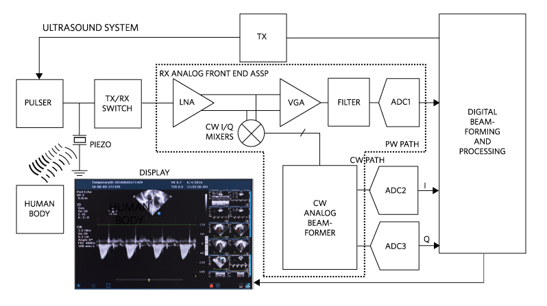
Fig 1. Ultrasound System (a Single Channel). (Credit: Maxim)
The ultrasound transmitter applies acoustic waves to the body. The ultrasound receiver picks up the echoes reflected from the body structure, typically by means of an array of piezoelectric transducers (Figure 1). The target is identified by the characteristic delay of the reflected pulse, with delays corresponding to distance traveled using Pulsed Wave (PW) transmission. In this mode, the VGA output is filtered, digitized, moved along the PW path and sent off for processing. To obtain accurate details of motion in the targeted area – for example, blood velocity in an artery – a continuous wave must be applied using Continuous Wave Doppler (CWD). In CWD mode, the extraction of the velocity and direction of the blood flow from the received Doppler-modulated signal requires a phase and frequency comparison to the transmitted signal. The comparison is performed using In-Phase/Quadrature (I/Q) demodulation. The system is configured so that either the PW path is enabled while the mixer array is powered down (PW mode), or the quadrature mixer array is enabled while the PW path is powered down (CWD mode).
From a partitioning standpoint, the entire PW path is often integrated into an analog front end (AFE) monolithic IC (ASSP). The AFE is tapped at the LNA output by the CW Mixers to produce the I, Q signals. The CW Analog Beamformer collects the I, Q signals from the entire array of transducers, aligns and sums them. The two beamformed signals are each digitized by external precision ADCs (ADC2 and ADC3 in figure 1) for information extraction and display.
The CW ADCs
The most important ADC spec for ultrasound applications is SNR. The motion of the transducer and the motion of body tissue (such as from patient breathing) causes very large low frequency signals that can be very close in frequency to the small blood signals of interest. A large SNR allows a definitive separation between the blood signals and these types of background signals.
The CW path’s bandwidth (BW) must be large enough for the expected Doppler shifts (20 kHz shift). With proper oversampling to maintain signal dynamic fidelity, the ADCs will require approximately 50x sampling or 1Msps. High sampling rate and high resolution (# of bits) both contribute to the high SNR required of the ADC. Another important requirement is low total harmonic distortion (THD), a measure of the non-ideality introduced by the ADC gain errors and non-linearity. THD adds up to a technology figure of merit.
Using high quality ADCs with very low THD to digitize the CW path will help resolve minute details and allows display of a high-resolution image on the screen.
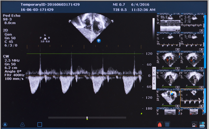
Fig 2. Heart Ultrasound (Credit: Maxim)
Fig 2 shows B-mode and CF images on the top and side and CW velocity peak detection on the bottom. This is an image taken from a patient with a bad heart valve. The negative cusps on the bottom image indicate the presence of a condition called tricuspid regurgitation.
The Ideal ADC for CW Ultrasound
The ideal ADC for this application would combine high resolution and high sampling rate with very low total harmonic distortion and good SNR. The MAX11905 fully differential SAR ADC (Figure 3) is a great fit for this application, as it has a THD of -121dB (as shown in Figure 4), high sampling rate (1.6Mbps), high resolution (20-bit), ultra-low power (8.4mW), and SNR (98.4dB).
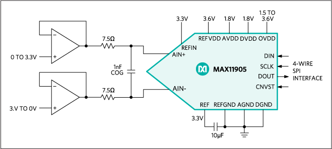
Fig 3. MAX11905 Application Diagram (Credit: Maxim)
MAX11905 has an excellent SNR (98.4dB, as shown in figure 4) and the best THD available in the industry (-121dB, as shown in Figure 4), almost 5x better than the nearest comparable device. In addition the MAX11905 has a high sampling rate (1.6Mbps), high resolution (20-bit), and ultra-low power (8.4mW), and excellent SNR (98.3dB).
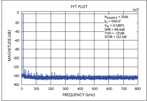
Fig 4. MAX11905 -121dB Total Harmonic Distortion (Credit: Maxim)
For space constrained applications a dual ADC, MAX11960, 20-Bit, 1Msps, Low-Power, Fully Differential SAR ADC is also available.
Conclusion
We have discussed the importance of preserving image clarity in medical ultrasound equipment and how this translates into a demand for excellent SNR, extremely low THD, high sampling rate and high resolution ADCs. MAX11905 20-Bit, 1.6Msps, Low-Power, Fully Differential SAR ADC excels in all the key criteria, making it an ideal choice for demanding ultrasound applications.
Glossary
ALIASING. The incorrectly reconstructed signal due to insufficient sampling.
ASSP. Application Specific Standard Product.
COLOR FLOW IMAGING. Combines anatomical information from ultrasonic pulse-echo techniques with velocity information from ultrasonic Doppler techniques to generate color-coded maps of blood velocity superimposed on grey-scale images of tissue anatomy.
CW BEAMFORMER. A device that takes multiple signals from the CW Doppler array, aligns and sums them together to extract coherent information.
CW IMAGING. Continuous Wave Imaging. Employs a constant or low frequency modulated ultrasound source. Continuous sending and receiving allows accurate measurement of target motion but cannot resolve its location; that task is
DOPPLER IMAGING. Imaging based on the Doppler Effect.
LNA. Low Noise Amplifier.
MSPS. Mega Samples per Second.
PW. Pulsed Wave Imaging. Employs a pulsed ultrasound source. Pulsed sending and then receiving allows accurate targeting of a given location: sound travels at constant velocity and delay in the returning pulse corresponds to distance. PW is less accurate than CW in resolving the target motion.
PWD. Pulsed-Wave Doppler.
SAR. A successive approximation (register)
SNR. Signal-to-noise ratio.
TRICUSPID REGURGITATION. A disorder in which the heart’s tricuspid valve does not close properly, causing blood to flow backward (leak) into the right upper heart chamber (atrium) when the right lower heart chamber (ventricle) contracts.
VGA. Variable Gain Amplifier.
ULTRASOUND. Sound wave above the 20 to 20,000 cycle (Hz) audible range.
About the Authors:
Nazzareno (Reno) Rossetti is a seasoned Analog and Power Management professional, a published author and holds several patents in this field. He holds a doctorate in Electrical Engineering from Politecnico di Torino, Italy.
Martin Mason is currently the executive director for Core-Signal Chain at Maxim Integrated Products. Prior to joining Maxim in 2008 he held product management and engineering positions at Actel, Atmel, Concurrent Logic, and GEC Plessey Semiconductors. He received a Bachelor of Engineering degree with honors in Microelectronics from the University of Newcastle Upon Tyne in the U.K.in 1989.