Hardware Design
This section describes how the circuit topology, range to measure, and resolution are determined.
One of the key decisions is to determine the topology of the circuit. Basically, there are two methods to measure an impedance. The system can apply current and measure the voltage across the impedance, or it can apply voltage and measure the current across the impedance. Besides, these signals can be dc or ac.6 It is important to analyze the advantages and disadvantages of each method.
There are dozens of circuits that measure ac and each one has its pros and cons. However, in order to accomplish the restrictions in performance, cost, and area, the following solution is considered as the best option.
The final decision is to use an ac voltage source as the excitation source and measure the current through the patient’s body to determine the skin conductivity. This solution avoids high voltages over single sweat glands, eliminating the danger of sweat gland damage and allowing the compliance of the IEC6060-1 standard. The ac signals eliminate the problem of electrode polarization.7
The current that must be measured needs to be digitalized, stored, and analyzed. It means the circuit will require an analog-to-digital converter (ADC). As most ADCs convert voltage and not current, the current through the patient’s body needs to be translated to voltage. This is carried out by a transimpedance amplifier (TIA). The noise specifications, size, and power consumption are three critical characteristics to choose the best operational amplifier, which will be used to implement the TIA.
Once the topology of the system is decided, the next step is to determine the range and resolution of the system under development.
Problems for the amplification of the EDA signal mainly stem from its wide range and the required high resolution. Typically, a skin conductance device must cover a range from 0 μS to 100 μS and it must also be able to detect 0.05 μS fluctuations. This resolution can be achieved using an ADC with at least 12-bit resolution. Regarding the resolution, the target in this project is 0.01μS, and, therefore, an ADC with 14-bit or 16-bit resolution is required.8
In order to get a resolution of 0.05 μS within a range of 100 μS while complying safety regulations, these blocks are required.
- An ac voltage source
- Protection elements to ensure compliance with IEC6060-1
- An electronic circuit to measure the current flowing through the patient’s body
Variations in the ambient temperature and skin temperature can produce changes in the EDA signal.9 Thus, it would be interesting to acquire the ambient temperature and skin temperature, too. It can be carried out by a simple thermistor plus several discrete components and an ADC.
Finally, power consumption is critical in this circuit. In order to reduce it and ensure the system is only activated when a new measurement is required, a power management unit must be also integrated. This block must be easily controlled by the main microcontroller and it has to supply all the EDA measurement circuit. Figure 1 shows the complete block diagram.
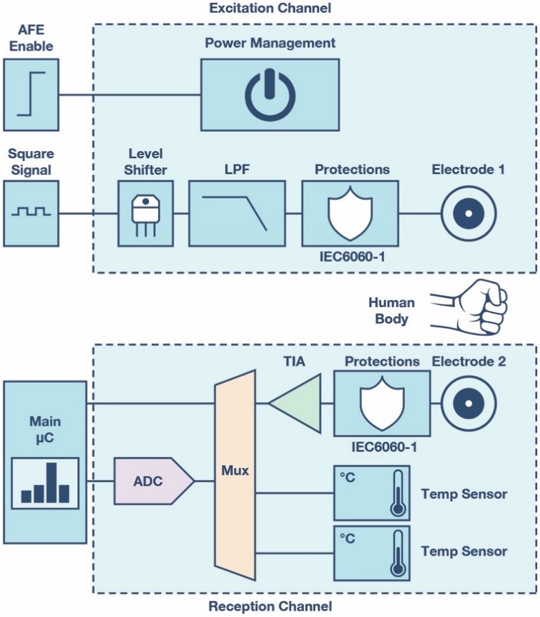
Figure 1. System block diagram.
In the following sections we will determine the best components for this application.
Power Management Unit
The decision is to use the ADP151 family to implement the power management unit due to several good features, and because its package and noise level are excellent for this application.10
Level Shifter
There are many ways and a broad range of integrated circuits to implement a level shifter. However, the area and price of those integrated circuits do not accomplish the restrictions of this project. Thus, the level shifter in this circuit was implemented by discrete components. Basically, it is formed by a transistor, DMN2990UFZ,11 and a resistor.
Low-Pass Filter and TIA
In order to implement the low-pass filter and the TIA, the ADA4505-2ACBZ is used as it has excellent power consumption, small size, and very low input bias current.12
ADC
The ADC that accomplishes all the system requirements is the AD7689BCBZ. This powerful ADC includes the voltage reference that can be turned off when it is not used in order to reduce the power consumption.13
Finally, in order to ensure the area constraint can be achieved, the minimum number of components and functionalities have been included and the smallest packages for all the components have been picked. Figure 2 shows the layout and size of this system.
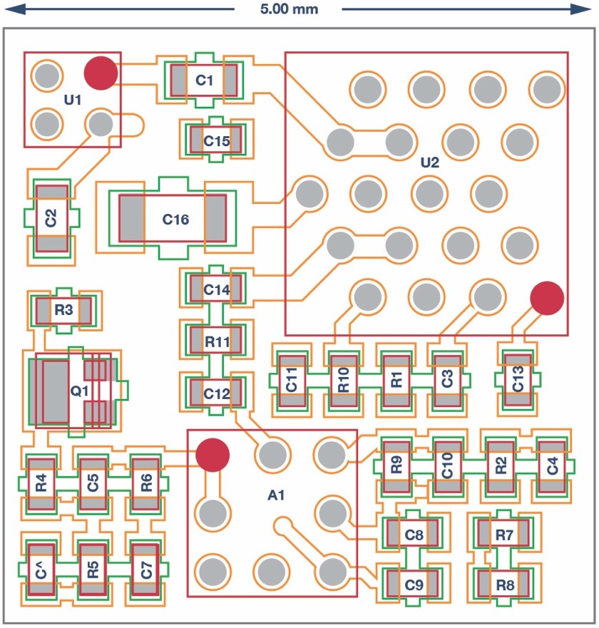
Figure 2. EDA discrete circuit layout.
Software Design
As mentioned previously, the system needs to generate an excitation signal in order to measure the conductivity of the skin. This excitation signal is an ac signal, and the two parameters, which can be extracted from an ac measurement, are the amplitude of the signal and the phase delay between the excitation signal and the acquired signal. The most important one is the amplitude, and there are several ways to obtain this parameter from an ac signal. However, the best method to obtain the amplitude in this system is to implement a discrete Fourier transform (DFT).14
The DFT can also be considered like a bank of filters and the level of attenuation is directly proportional to the number of samples, and the position of the maxima depends on the excitation signal.
At this point, a good argument would be to use a big number of samples (N) to implement the DFT since it would improve the SNR. However, the power consumption of the DFT (if implemented directly) is proportional to the number of samples and we will need more power as we acquire more samples. This means that there is an important trade-off between the number of samples and the power consumption.
Another important parameter is the ratio between the sampling frequency and the excitation frequency. The equation that implements the DFT is very simple if the sampling frequency is 4× the excitation frequency. In this case, the complex equation involving floating-point multiplications turns into additions. Multiplications can be bearable if the available processor is a DSP or a Cortex®-M4. However, this can be an important problem when the calculation must be implemented in a Cortex-M0. Compare Equation 1 to the filter notation of a single-point DFT calculation for a 100 Hz bin (FCENTER) when the sampling frequency (FS) is 400 Hz and 500 Hz.
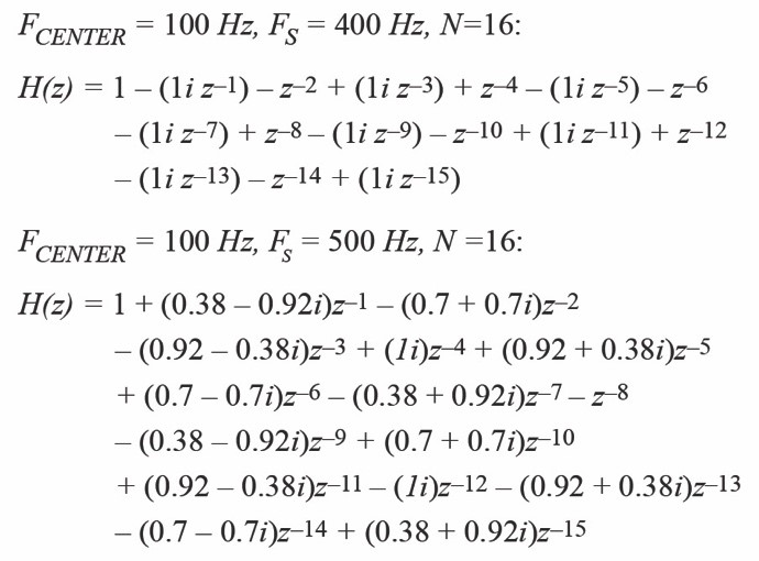
Equation 1
Once the technique to apply and the ratio between the excitation frequency and the sampling frequency are clear, the next step is to determine the excitation frequency.
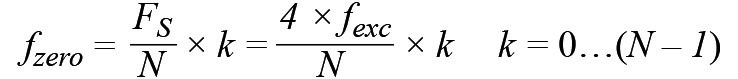
The excitation frequency must be as low as possible to ensure the current will flow through the patient’s skin and it will not penetrate into the body.15 Therefore, the excitation frequency must be smaller than 1 kHz. It must also be mentioned that the main source of noise in this application is the 50 Hz/60 Hz noise due to the power mains.
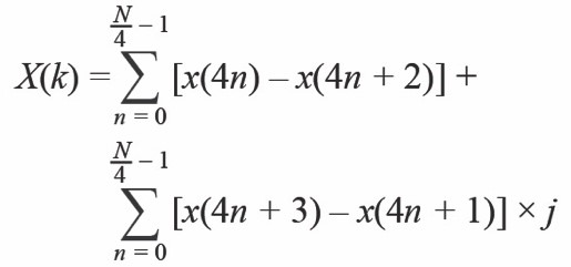
Equation 2 shows that each component of the DFT, X(k), nulls the contribution of the spectral components of the form n × FS/N where n = 0, 1, 2, and through N – 1, except for when N = k. By properly defining the excitation frequency we may cancel the contribution from the 50 Hz noise source. However, a high frequency cannot be used due to the previous arguments. Thus, a good trade-off is 100 Hz, although we may capture the harmonics of the main’s interferer.
If the excitation signal is 100 Hz and the sampling frequency is 400 Hz, the zero at 50 Hz appears when N is equal to 8, 16, and 32. We must also keep in mind the number of samples must be as small as possible to minimize power. Thus, a good trade-off is to use 16 samples to implement the DFT. The number of samples can be increased in order to improve the SNR if it is required. Of course, if the noise is the 60 Hz noise instead of the 50 Hz, the sampling frequency should be 480 Hz and the excitation frequency should be 120 Hz. The frequency response is shown in Figure 3 and the mathematical equation, which only involves addition, is shown in Equation 3.
Equation 2.
Equation 3
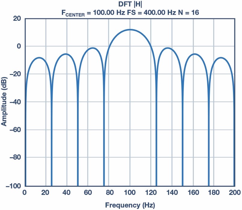
Figure 3. DFT can be considered a bank of filters. This is the DFT frequency response with 16 samples, a sampling frequency 400 Hz, and a center frequency of 100 Hz with a rectangular window.
Mechanical Design
An evaluation system was developed to test and prove this proposed solution. The platform is composed of the main sensors required in EDA measurements and some other indispensable features. Movement and temperature may affect the skin impedance measurement.9, 16 Therefore, signals capturing motion and temperature are also obtained.
The system also includes a battery charger to recharge the LIPO battery used in this platform. This device requires a battery with high capacity, as we want to enable 24 hour acquisitions. Impedance, temperature, and acceleration measurements are saved in a file which is stored in a micro SD card or the data can be sent by Bluetooth® low energy to a tablet or PC. Figure 4 shows the evaluation platform.
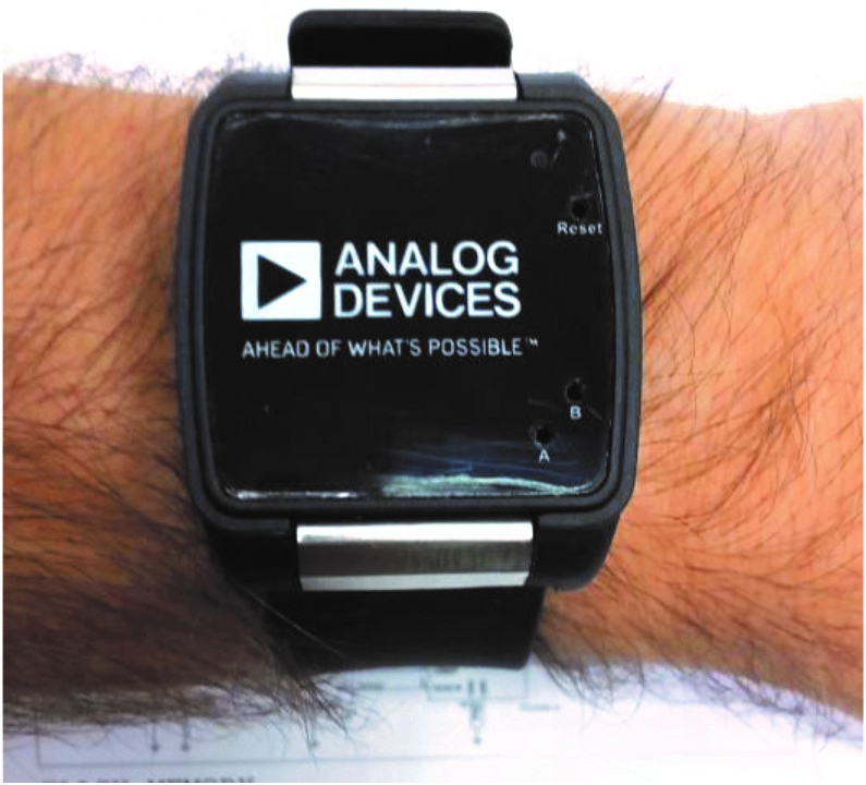
Figure 4. EDA evaluation platform. ADI watch GEN II.
References
6 Wolfram Bouscein. “Introduction to Electrodermal Measurement” Electrodermal Activity, pp 88-103, Springer U.S., 2012.
7 Banu Onaral, Herman P. Schwan, Banu Onaral. “Electrical Properties of Bioelectrodes.” IEEE Transactions on Biomedical Engineering, December, 1984.
8 Wolfram Boucsein. “Specific Problems of Electrodermal Measurement.”Electrodermal Activity, pp 96-98, Springer U.S., 2012.
9 Wolfram Boucsein. “Climatic Conditions.” Electrodermal Activity, pp 189-192, Springer U.S., 2012.
10 ADP151 Data Sheet. Analog Devices Inc., 2017.
11 DMN2990UFZ Data Sheet. Diodes, 2015.
12 ADA4505-2 Data Sheet. Analog Devices Inc., 2017.
13 AD7689 Data Sheet. Analog Devices Inc., 2017.
14 Julius O. Smith III. “Mathematics of the Discrete Fourier Transform (DFT): with Audio Applications.” Stanford University, 2002.
15 Wolfram Boucsein. “Exosomatic Recording with Alternating Current.”Electrodermal Activity, pp 126-129, Springer U.S., 2012.
16 Wolfram Boucsein. “Physiologically Based Artifacts.” Electrodermal Activity, pp 141-143, Springer U.S., 2012.
About the Authors
Javier Calpe [javier.calpe@analog.com] received his B.Sc. in 1989 and his Ph.D. in physics in 1993, both from the Universitat de Valencia, Spain. Javier is the site manager of ADI’s development center in Valencia, Spain.
Jose Carlos Conchell [jose.conchell@analog.com] is a product applications engineer in the Industrial and Healthcare Business Group, based in Valencia, Spain. He focuses on bioimpedance applications. José Carlos Conchell joined ADI in 2011. He received his B.Sc. and M.Sc. degree in electrical engineering and M.Sc. degree in biomedical engineering from Universitat de Valencia, Spain, in 2007, 2010, and 2016 respectively.