Improved accuracy measurement in linear ball rail system benefits medical applications such as imaging, radiation treatment, and bone density measurement. This exclusive article examines common concerns with traditional rail systems and how this new technology offers a solution to them.
| Top: Pivoting or rolling about the X, Y, and Z axis can be defined as roll, pitch, and yaw | |
Bottom: Cross roller slides are the most commonly used product for high accuracy applications but typically do not work well for strokes over 600 mm. | |
At a Glance
• Traditional concerns
• Rail and block systems
• High precision need
• Ball rail solution
In virtually any type of application requiring precision linear motion, linear rails have become the most common form of linear guidance. Increasing load capacities, improved rigidity, reduced friction, and lower noise are all characteristics that make the typical linear rail and runner block system an excellent option, providing high performance in a compact footprint when moving something from side-to-side.
A linear guide consists of a re-circulating ball or roller bearing mounted on a profiled rail. The re-circulating rolling elements allow for very low friction and high efficiency of translated motions. There are no complex lubrication systems required as with sliding friction technologies like traditional box ways—once the standard used in many high-end machine tools.
Rail and block systems typically range in size from 7.0 mm for very small instruments to 125 mm for large machine tools or aerospace applications with large loads. They are easy to specify, order, install, and maintain. As a result, engineers have come to prefer these re-circulating, anti-friction bearings for guiding motion in advanced, high-tech applications. In the medical field, this would include applications such as machine beds, liquid handling devices, and medical testing and sampling equipment.
Traditional boxway slides require complex lubrication systems and gib adjustment. |
As machines become more capable, the demand grows for even greater performance in linear guides. Designers begin to create solutions that were unfathomable with previous technology.Sometimes seemingly unrelated technologies drive progress in each other. For example, it may be difficult to see an immediate connection between advanced 3D imaging techniques, computer modeling, and the need for improved precision in linear guidance systems. But that’s exactly how technology moves forward. For example, a doctor can now look at a human heart using what essentially is a high-end video system instead of surgery. He quickly develops a desire for sharper images with greater detail. This in turn leads medical equipment designers to seek more precision in moving and positioning their imaging systems, which then leads linear guide manufacturers to develop rail and block systems with ever-increasing precision. The patient benefits in the form of less invasive diagnostic techniques.
The High-Precision Challenge
In the world of very precise linear guides, how can they be even more accurate, especially in a world increasingly defined in terms of nanotechnology?Accuracy measurement in linear guides is defined by the height and width variation as measured from the middle of the runner block. |
Accuracy in linear guides depends on many factors: the trueness of the rail on which the runner block or bearing travels; the raceways inside the bearing through which the balls or rollers travel; the operating environment; the flatness of the rail mounting surface; and other factors. Among high-performance linear bearings, the most important area of refinement is the smoothness of ball re-circulation inside the runner block as it travels along the rail.
Applications at the very high end of the accuracy spectrum, such as gauging, bone density measurement, radiation treatment, microelectronics—even high-end metal cutting—can be adversely affected by any roughness in the bearing tracks. This roughness can sometimes even be felt by hand as small pulsations from the balls traveling over the rough areas. These pulsations cause pivoting or rotation of the bearing about its axis. For extremely precise applications, this rotation is magnified when transmitted over a distance to a measurement point. Even minute movement of the balls in the re-circulation chamber can cause dramatic differences in machine output. As a result, the most commonly used product for high-accuracy situations has traditionally been the cross roller slide because there are no re-circulating components. However, the lack of re-circulating components in the cross roller slide also leads to stroke limitations. Typically, anything over 600 mm is simply too long. In addition, cross roller slides lack the load capacity and rigidity of linear guides. Therefore, this type of linear guide would not work for an MRI machine or x-ray machine with longer strokes.
So how does an engineer achieve the desired accuracy if the cross roller slide will not fit the application? How can he be confident that the desired accuracy will be achieved? The answer lies in the development of new measurement techniques to define accuracy within the linear guide.
Minimizing Pitch, Roll, and Yaw
Normally, accuracy measurements in linear guides are defined by the height and the width variation as measured from the middle of the runner block. However, measurement of height and width alone do not account for any pivoting of the bearing about the X, Y, or Z axis. In other words, although the height or width of the bearing may be extremely accurate when measured from the middle of the runner block, there may be some inaccuracy about the center line of the bearing due to ball pulsation—causing the bearing to slightly rotate about its axis. These movements are known as pitch, roll, and yaw.Enhancements to the ball raceways result in 60% less deviation as the high-precision runner block travels along the rail. |
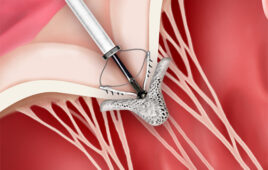
What can be done to minimize pitch, roll, and yaw? The solution is to alter the geometry of the re-circulation pathways and eliminate roughness at key transition points. Three key transition points in a typical linear bearing are the entry zone, the load zone (where the ball is actually under load), and the exit zone.
| Optimized entry and exit zone raceways reduce rolling, pitching, and yawing deviations. |
The entry zone is the point just before the ball enters the load zone. At this point, the ball is circulating through the end of the bearing and is rounding some critical radii before it re-enters the load zone. As it passes these points, the rotation of the ball can be affected by surface roughness and contact angles inside the bearing, creating friction as well as additional unwanted motion.In the load zone, the ball is rotating and motion is typically consistent with uniform ball spacing. But as it approaches the exit zone, it goes from a point of load to no-load and is shot out of the load zone into the end of the bearing. This exit zone area is characterized by inconsistent ball spacing and ball-to-ball contact due to balls being shot from the load zone. Interactions in each of these key transition points lead to ball pulsations that can be felt when moving the bearing by hand. It is these ball pulsations which ultimately cause rocking motions that affect the overall smoothness of travel and therefore, affect the resulting precision of a machine measuring bone density, 3D coordinate measurement, or other highly accurate medical device.
High-Precision Ball Rail
Using a newly developed high-precision ball rail system, medical device manufacturers can overcome these limitations by optimizing the ball re-circulation and consistently providing extremely smooth motion with this technology as the balls circulate in the bearing raceways. This is accomplished through the use of a steel insert and relief zones that dampen the ball entry forces at the ends of the bearing. This eliminates the rough motion and rolling of the ball rail system about its axis and creates not only accurate height and width dimensions, but also reliable linear motion about all axes. Tests show a 60% reduction in pitch, roll, and yaw compared to standard linear guide systems.With the emergence of super-precise linear guides, now more than ever, designers of high-tech applications can begin the next generation of machines to help improve the lives of consumers and patients. As the demand grows for even tighter tolerances, linear guide manufacturers will surely step in to meet that demand.
Online
For additional information on the technologies and products discussed in this article, visit Bosch Rexroth Corp. at www.boschrexroth-us.com
Milton Coleman is a product manager for linear guides with the Bosch Rexroth Corp. linear motion and assembly technology group, 816 E. Third St., Buchanan, MI 49107. He has 12 years of experience in the linear motion industry and earned his BSE in mechanical engineering from Duke University. Coleman can be reached at 800-322-6724.