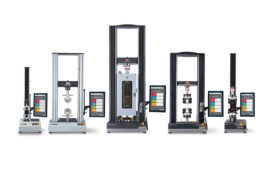
The following was excerpted from Aerotech’s Linear Motors Application Guide, which is available for free download from the Aerotech website.
A linear motor can be flat, U-channel, or tubular in shape. The configuration that is most appropriate for a particular application depends on the specifications and operating environment.
Cylindrical moving magnet linear motors
In these motors, the forcer is cylindrical and moves up and down a cylindrical bar that houses the magnets. These motors were among the first to find commercial application, but do not exploit all of the space saving characteristics of their flat and U-channel counterparts. The magnetic circuit is similar to that of a moving magnet actuator. The difference is that the coils are replicated to increase the stroke. The coil winding typically consists of three phases, with brushless commutation using Hall effect devices.
The forcer is circular and moves up and down the magnetic rod. This rod is not suitable for applications sensitive to the leakage of magnetic flux. Because the motor is completely circular and travels up and down the rod, the only points of support are at the ends. This means that there will always be a limit to length before the deflection in the bar causes the magnets to contact the forcer.
U-channel linear motor
The U-channel linear motor has two parallel magnet tracks facing each other with the forcer between the plates. The forcer is supported in the magnet track by a bearing system. The forcers are ironless, which means there is no attractive force and no disturbance forces generated between forcer and magnet track. The ironless coil assembly has low mass, allowing for very high acceleration.
Typically the coil winding is three phase, with brushless commutation. Increased performance can be achieved by adding air-cooling. This design is better suited to reduced magnetic flux leakage due to the magnets facing each other and being housed in a U-shaped channel.
Due to the design of the magnet track, they can be added together to increase the length of travel, with the only limit being the length of the cable management system, encoder length available, and the ability to machine large, flat structures.
Flat-type linear motors
There are three designs of these motors: slotless ironless, slotless iron, and slotted iron. Again, all types are brushless. To choose between these types of motors requires an understanding of the application.
Slotless-ironless flat motors
The slotless-ironless flat motor consists of a series of coils mounted to an aluminum base. Due to the lack of iron in the forcer, the motor has no attractive force or cogging, which helps with bearing life in certain applications. Forcers can be mounted from the top or sides to suit most applications.
Ideal for smooth velocity control such as scanning applications, this type of design yields the lowest force output of flat-track designs. Generally, flat magnet tracks have high magnetic flux leakage.
Slotless-iron flat motors
The slotless-iron flat motor is similar in construction to the slotless-ironless motor except the coils are mounted to iron laminations and then to the aluminum base. Iron laminations are used to direct the magnetic field and increase the force.
Due to the iron laminations, an attractive force is now present between the forcer and the track and is proportional to the force produced by the motor. As a result of the laminations, a cogging force is now present on the motor. This motor design produces more force than the ironless designs.
Slotted-iron flat motors
In this type of linear motor, the coil windings are inserted into a steel structure to create the coil assembly. The iron core significantly increases the force output of the motor due to focusing the magnetic field created by the winding. There is a strong attractive force between the iron-core armature and the magnet track, which can be used advantageously as a preload for an air-bearing system. However, these forces can also cause increased bearing wear at the same time. There will also be cogging forces, which can be reduced by skewing the magnets.